|
R C O P T I C A L S Y S T E M S
Telescope Users Guide
|
RC Optical Systems 4025 E. Huntington Drive, Suite 105 Flagstaff, Arizona 86004 Phone 928-526-5380 Email - info@rcopticalsystems.com
|
! ! ! W A R N I N G ! ! !
|
RCOS telescopes are not made for daytime use. It IS imperative that these telescopes be kept out of direct sunlight.
NEVER LOOK (THROUGH THE TELESCOPE) AT THE SUN AS INSTANT BLINDNESS WILL OCCUR!
|
Table of Contents:
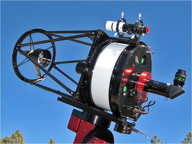
RCOS telescopes now ship with an optional integrated control system, the Telescope Command
Center (TCC) to maximize performance and permit remote operation of key telescope parameters.
Depending on your specific option configuration, you may have some or all of these features.
For remote operation, all are needed; if you are operating the scope locally, they are a great
convenience but not absolutely necessary.
The TCC provides complete control for telescope cooling, heating (for dew control) and
secondary focusing.
Additionally the TCC controls camera rotation, if the telescope is
equipped with the Precision Instrument Rotator (PIR). These functions can be controlled
locally via a hand controller or remotely via a Windows-based application that runs on the
controlling PC. For detailed information on the TCC, see the very complete and detailed help
file that comes with the TCC application. Screen shots used in this document will come from
the PC application. Note that the TCC application has a very extensive and well-written Help
section. This is definitely recommended reading.
The RoboFocus controller is a lower cost alternative to the TCC for secondary focusing only.
It consists of a control box and a Windows-based application that allows local or remote
focusing of the secondary mirror. Local focusing gives no indication of focus position. Using
the RoboFocus Control Program (RFCP), you can control focus remotely.
The design of a Ritchey-Chrétien telescope requires the spacing between the primary and
secondary mirror be close to their design center. Since this is spacing cannot be directly
measured easily, RCOS specifies a back focus distance (BFD) for each telescope it produces.
This BFD corresponds to the design center mirror spacing. It is then up to the user to achieve
this BFD through a combination of the camera and accessories, extension tubes and the Fixed
Instrument Adapter or Precision Instrument Rotator. Fine focusing is then best done by slight
movement of the secondary focuser, usually electronically.
One of the challenges in developing one's instrument stack-up that contributes to the BFD is
determining the actual spacing and distances of various pieces and parts. Below is a table of
measurements for various instruments, adapters, etc. If yours is not on the list, you will
have to measure the appropriate dimension to add to your optical path length calculation.
|
Item
|
Note
|
Inches
|
|
SBIG ST-8/9/10
|
3
|
0.66
|
|
SBIG CFW-8A
|
2
|
1.00
|
|
SBIG AO-7 (SBIG spec)
|
|
3.50
|
|
Muscle Plate
|
4
|
0.19
|
|
SBIG AO-7 D-block + 2xT-thread
|
1
|
0.34
|
|
SBIG AO-7 Mirror box
|
1
|
2.52
|
|
SBIG AO7 captain's wheel
|
1
|
0.75
|
|
RCOS FIA base
|
6
|
0.25
|
|
RCOS Instrument Rotator (PIR)
|
5
|
2.81
|
|
RCOS Extension tube
|
|
2.50
|
|
RCOS Extension tube
|
|
2.00
|
|
RCOS Extension tube
|
|
1.75
|
|
RCOS Extension tube
|
|
1.25
|
|
RCOS Extension tube
|
|
0.75
|
|
SBIG T-thread - SCT adapter
|
|
0.71
|
|
AP ADA204 2.7" - SCT adapter
|
|
0.73
|
|
AP ADA2003 2.7" - 2" nosepiece
|
|
0.75
|
|
AP ADA2013 2.7" - 2" nosepiece
|
|
0.38
|
|
Van Slyke ZPTA 2" nosepiece
|
|
0.00
|
|
Optec 2" nosepiece
|
|
0.25
|
|
Optec Intelligent Filter Wheel
|
|
0.92
|
|
RCOS T-thread - 2.7" adapter
|
|
0.38
|
Notes:
- These are actual measurements and for some reason, do not add up to the SBIG spec for the
assembly.
- This dimension includes the impact of the output window.
- This dimension includes the impact of the filter glass.
- This dimension represents the increased thickness over the standard CFW-8 cover
plate.
- The actual dimension from the front of the PIR to the back of the mounting flange is
2.94". The number reported here assumes a 0.13" back plate counter-bore i.e., how much the
mounting surface for the PIR is inset into the back plate. If your counter-bore were deeper,
for example 0.38", then the corresponding table entry would be 2.56".
- The actual dimension from the front of the FIA base to the back of the mounting flange is
0.38". The number reported here assumes a 0.13" back plate counter-bore i.e., how much the
mounting surface for the PIR is inset into the back plate. If your counter-bore is deeper, for
example 0.38", then the corresponding table entry would be 0".
|
As an example, consider a setup consists of an ST-8E/CFW-8A, AO-7 hard mounted to the Muscle
Plate; SBIG captain's wheel attached to an AP ADA204 and using an RCOS PIR gives:
0.66 + 1.00 + 0.19 + 2.30 + 0.75 + 0.73 + 2.81 = 8.44"
Assume a BFD of 9.24". The required spacer to achieve the correct BFD is 9.24 - 8.44 or 0.80".
Using the standard RCOS 0.75" Extension Tube gets within 0.05".
If you use multiple instrument arrangements, for example with and without an AO-7, you will
need to repeat the spacer calculation for each arrangement. The accuracy should be as close as
practical. Staying within 1/8 inch would guarantee any optical performance degradation would
be insignificant, although tolerances as large as ½ have been reported as workable.
Once the appropriate back focus is set, all remaining focusing is done with the secondary focuser.
Much has been written on how to achieve optimal focusing and will not be repeated here. For
example, see Ron Wodaskis The New CCD Astronomy, Chapter 2, for tips and techniques. This
document will concentrate instead on the mechanics and usage of the equipment with your telescope.
The Help Topics of the TCC application provides much in-depth information about all the
features and facilities of the TCC. This section should be considered a quick-start guide.
The secondary focuser is driven by a servo-controlled motor that moves the secondary mirror in
and out.
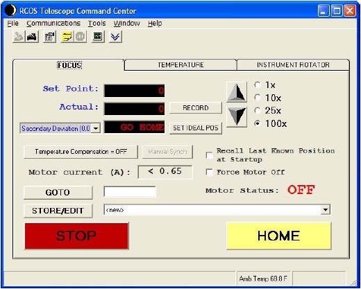
Figure 1, Focus Tab before homing
Figure 1 shows the focus tab at first power up. In order to establish the focusers reference
position, the secondary must first be HOMED. This sets the nominal zero point for the
secondary translator and places the secondary mirror furthest from the primary. Note the GO
HOME reminder next to the Secondary Deviation pulldown.
Note that you can move the focuser in by the top button (up arrow) and out by the bottom
button (down arrow). You can move in count steps of 1, 10, 25 or 100 counts. You can also go
to an absolute position by entering a value next to the GOTO button and hitting that button.
Home the focuser by pressing the Home button. Next, set the focus position to 8000 or so by
entering 8000 in the window next to the GOTO button. Confirm the slew and the focuser will
move to that position. Slew the telescope to a bright star and change your focus position
count with either the hand controller or PC application, while noting whether the star size
increases or decreases. Initially use the coarse setting on the hand controller or the 100x
steps on the application to reduce the star size, indicating you are approaching focus. As you
get closer, use the fine setting or the 25x or 10x steps on the application. Once you have
achieved optimal focus (minimum star size), and assuming you have set the BFD correctly as
above, this is your IDEAL POSITION. Hit the SET IDEAL POSITION and the entry will be 0.00.
Also, check the box Recall Last Known Position at Startup. Next, hit the record button. The
focus position is now recorded in TCC flash memory. It will also be recorded automatically if
the position is unchanged for 3 minutes. Once recorded, you can turn off power to the TCC and
the focus position readout will be maintained upon next power up.
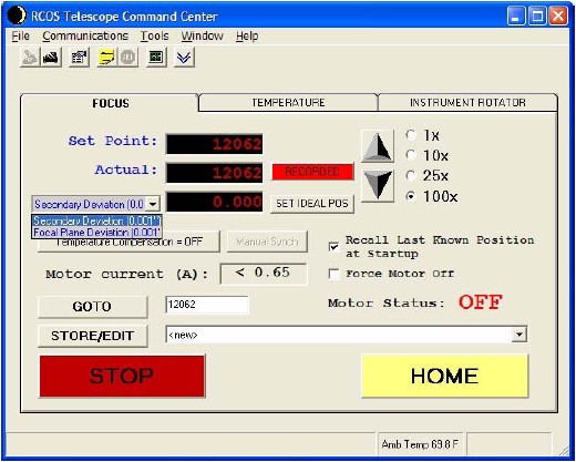
Figure 2, Focus tab after homing
Figure 2 shows the focus tab after a power cycle. Note the focus position of 12062 is
maintained. Also note the pull down Secondary Deviation (0.001) and Focal Plane Deviation
(0.001). Assuming you have focused in native mode, i.e., without any reducers and have
calculated the BFD correctly as above, this is a very useful indicator. Because each focuser
count corresponds to 1/40000, the readout is a precise indicator of secondary travel and
therefore mirror spacing in terms of secondary deviation. It also provides a rough indicator
of focal plane deviation, assuming an F/9 focal ratio. These readouts can be used to see how
much you deviate from the correct spacing as you change your optical configuration with
reducers, adding an AO7 or other optical components.
You can use the Store/Edit function on the application to save that position and an
appropriate description with the application. See the TCC Help Topics for detailed steps to do
this.
The TCC firmware will maintain the last focus position in flash memory, as long as the focus
position is unchanged for a period of 3 minutes, before powering down.
Based on a nominal F/9 focal ratio and the translation resolution of the TCC focuser of 0.025
mils/count, the Critical Focus Zone for the scope is approximately 40 counts. What this means
is you should see little change in star size as you move over a range of 40 counts. Unless
your seeing is very good, you will see changes in star size, especially if you are using a CCD
camera.
In general, the design of RCOS telescopes is such that there is little or no temperature
coefficient of focus. However, should you have a very critical application and can determine
that you have a repeatable temperature coefficient of focus, you can enter that coefficient
via the Temperature Compensation button. TCC will then adjust the focus point in accordance
with the ambient temperature. See the TCC Help Topics for detailed steps to do this.
Note that the TCC application is a fully ASCOM-compliant focuser and as such works well with
FocusMax, an automatic focusing program, available at http://www.focusmax.org. Version 3 is
recommended, currently in beta at this writing.
The secondary focuser is driven by a stepper motor that moves the secondary mirror in and out.
The RoboFocus (RF) has a number of setup parameters that must be entered in the RoboFocus
Control Program (RFCP).
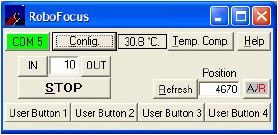
Figure 3, RoboFocus Control Program
Here are some recommended starting points to enter into the RoboFocus Config page:
|
Setup Paramter
|
Value
|
|
Duty Cycle
|
20%
|
|
Microstep Pause
|
4
|
|
Step Size
|
2
|
|
Max. Travel
|
27468
|
|
Backlash Direction
|
IN
|
|
Backlash Amount
|
4
|
The maximum travel will depend on how you calibrate your RF. Follow the instructions in the RF
documentation. Determine the direction that moves the secondary out. Move the secondary out
until motion stops and set that point at 0. Then run the RF calibration in to set the maximum
travel. The total travel of the secondary translator is around 1 so around ¾ should be
sufficient. In the above example, the maximum travel was around that amount.
Focus is most easily done using the RFCP. Slew the telescope to a bright star and begin to
increase your focus count. Start with large steps out of around 100 counts and hit the IN
button. As you get closer to focus, change the step size to 25 and then 10 to get closer to
focus. Once you have achieved optimal focus (minimum star size), note the position for future
reference. The setting is maintained in the RF so subsequent power cycles will come up at the
same setting. You can then fine-tune focusing from there if required.
For the above setup parameters, and based on a nominal F/9 focal ratio, the Critical Focus
Zone for the scope is approximately 30 counts.
In general, the design of RCOS telescopes is such that there is little or no temperature
coefficient of focus. However, should you have a very critical application and can determine
that you have a repeatable temperature coefficient of focus, you can enter that coefficient
via the Temp Comp Button. Once properly setup, RoboFocus will adjust the focus point in
accordance with the ambient temperature. See the RoboFocus Help for detailed steps to do this.
Note that the RoboFocus application is a fully ASCOM-compliant focuser and as such works well
with FocusMax, an automatic focusing program, available at http://www.focusmax.org. Version 3
is recommended, currently in beta at this writing.
As with any telescope, it is important for the optics to be close to thermal equilibrium with
the ambient temperature. The primary mirror represents a significant thermal mass and cools
slower than the ambient. Failure to have the primary mirror close to the ambient temperature
can give rise to tube currents, which can distort the image. This can be seen most clearly
with a high magnification eyepiece.
The RCOS telescope design incorporates three cooling fans whose function is to draw cool air
down the tube around the primary mirror to help it cool faster. Truss designs will cool faster
than closed tube designs. Best cooling is achieved with the telescope pointed near the zenith.
For telescopes without the TCC, it is recommended that the fans be engaged for 1.5 2 hours
for the closed tube designs and 1 1.5 hours for truss designs. This can be accomplished by
using a 12-volt power supply plugged into the fan power jack on the back plate. It accepts a
5.5/2.1 mm coax power jack, center positive. Fan speed control is possible via the adjustable
12-volt power supply.
For telescopes with the TCC, see below.
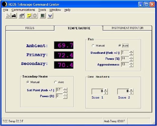
Figure 4, TCC Temperature Control Tab
Figure 4 shows the TCC temperature control tab. All temperatures are in degrees Fahrenheit.
Readouts are provided for ambient, primary mirror and secondary mirror. The secondary mirror
is also equipped with a heater that is controlled by the TCC. Additional heaters can be added
and manually controlled by the TCC via the Zone 1 and Zone 2 heater controls.
The Fan box is used to control the speed of the primary fans. Figure 4 shows the fans on
automatic with the target of getting to and keeping within 2 degrees of ambient. This is a
recommended starting point. The control system will adjust the voltage to the fan, and thus
the fan speed to keep the primary mirror within the specified offset to ambient. Typically the
fans come on at 100% when started and slow down, as the temperature difference gets smaller.
Be sure to read the fan threshold section of the TCC Help Topics for insuring maximum
adjustment range for your specific fans. Minimal vibration generally occurs with lower
rotation speed. This in turn allows keeping the primary close to the ambient temperature
during imaging or viewing applications. The fans can also be placed on manual control if
desired. If you want to turn off the fans, place the Fan control on manual and set Power (%)
to 0. The details are explained in the TCC Help Topics.
The secondary heater is useful in humid environments. Since the secondary mirror is at the top
of the tube, or totally exposed with the truss design, it will cool to ambient quickly. If the
dew point is close to ambient, it is not unexpected for condensation to form on the secondary.
By using the secondary heater and the built-in control system, it is possible to keep the
temperature of the secondary above ambient to prevent dew formation without significantly
impacting imaging.
To use this feature, it is first necessary to run the secondary calibration wizard under the
Tools menu. Follow the on-screen instructions to perform this calibration. Once calibrated,
you can set the Secondary Heater to Auto and adjust the Set Point for the desired temperature
above ambient. A good starting point is +2. (Note that it is possible to adjust the Set Point
plus and minus. For dew prevention, the value should be positive.) The Power will adjust as
needed to maintain this temperature. This is a slow control loop and you may not see any
temperature change right away. Allow 30 minutes or more to for the heater power to increase,
depending on the set point and difference desired.
In extremely humid environments, it is possible to locate a strip heater on the primary mirror
and control it manually via the Zone 1 or Zone 2 Dew heater control. Adjust the power and note
the temperature of the primary mirror. Again, this is a slow responding effect.
This optional accessory allows rotating the camera to frame a target or acquire a guide star
for an autoguider. It is controlled in a manner similar to the Focuser. It must first be homed
but once it is, it retains its rotational position throughout power cycling.
There are two home sensors for the rotator, one at 0° and one at 180°. First, home the
rotator. If you are using a camera or any other instrument with attached wires, it is
advisable to use the hand controller to manually rotate through a range to insure any cables
do not wrap excessively or otherwise hang up. Once this range is noted, keep it in mind while
using the TCC application.
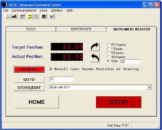
Figure 5, Instrument Rotator Tab
In Figure 5, note that the target and actual position is shown as 23 degrees. It is possible
to move the rotator clockwise (upper curved arrow button) and counterclockwise (lower curved
arrow button. You can move it in the amount indicated by the buttons at 0.5 degree, 1 degree,
5 degrees, 45 degrees or one you enter in other. You can also specify an absolute rotation
via the GOTO entry. Finally, you can store/edit entries as desired.
The power of this accessory is most apparent when used in concert with a precise planetarium
program. One example of such a program is TheSky. One can perform an image link in TheSky and
know the precise orientation of the camera. If a guide star appears within range of TheSkys
Field of View indicator, one can simply note how far the image must be rotated for the guide
star to fall on the guide chip and rotate that amount.
Telescope Users Guide | Modified on July 17, 2005 Copyright © 2003 RC Optical Systems All Rights Reserved
|